... Which Works Better The Right Way Around
Even though I was still reeling from the implications of capacitors and resistance, I forged on to the next project, which introduced the mighty transistor. Allegedly these things are useful for stuff.
The circuit I set up looked pretty familiar: it was a lot like the one I built when I was playing with the relay in project 7, and it turns out this is because relays and transistors are fundamentally the same thing: switches controlled by electricity. In fact, the book contained a handy chart describing the pros and cons of using each one in any given situation.
There was also a small footnote that explained that the very specific transistor I have in my box is a P2N2222A, and not a PN2222A as used in the diagram. This means that the flat side needs to go the other way around from the picture, or else it won't work. Arrrrgh. Which side of a transistor gets flattened seems like the kind of thing we could have standardized on some time in the last 60 years...
(Note to self: Next multimeter I buy is going to have a transistor testing function.)
Anyways, once it was actually wired up correctly, it worked as expected: By sending a little voltage to the "base" pin, I could pass more voltage along the main circuit and light up an LED. Woohoo!
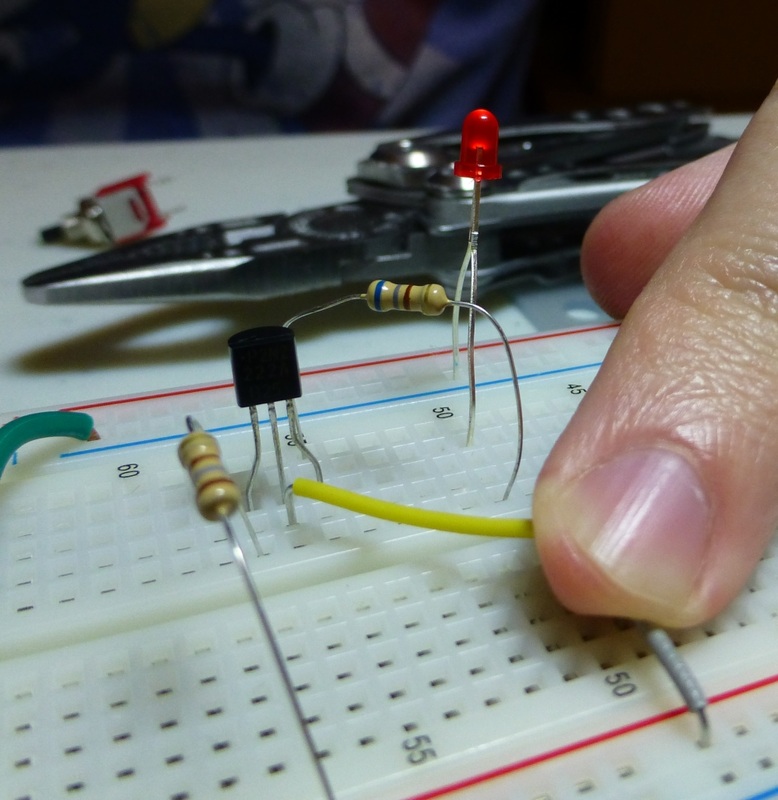
(For the record: A transistor has 3 pins. The Base pin is the "switch", which allows current to flow from the "collector" pin to the "emitter" pin.)
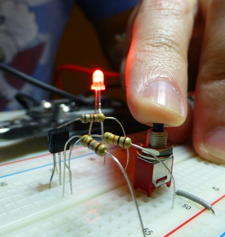
Further testing demonstrated that this transistor works as an amplifier as well: By using my finger in place of the pushbutton switch, I could provide a very high resistance connection to the base pin. This made the LED glow just a tiny amount. By wetting my finger (to lower resistance) I could get the LED to glow more. In both cases, the current was significantly lower to the base than to the collector pin, and the current coming through the transistor was rising and falling relative to the current going to the base.
This means you could have a weak signal going to the base, and "amplify" it into a strong signal through the transistor. This is kind of amazing, I have wondered for years how exactly amplification works, how exactly one "beefs up" a signal. Now I know (at least one way)!
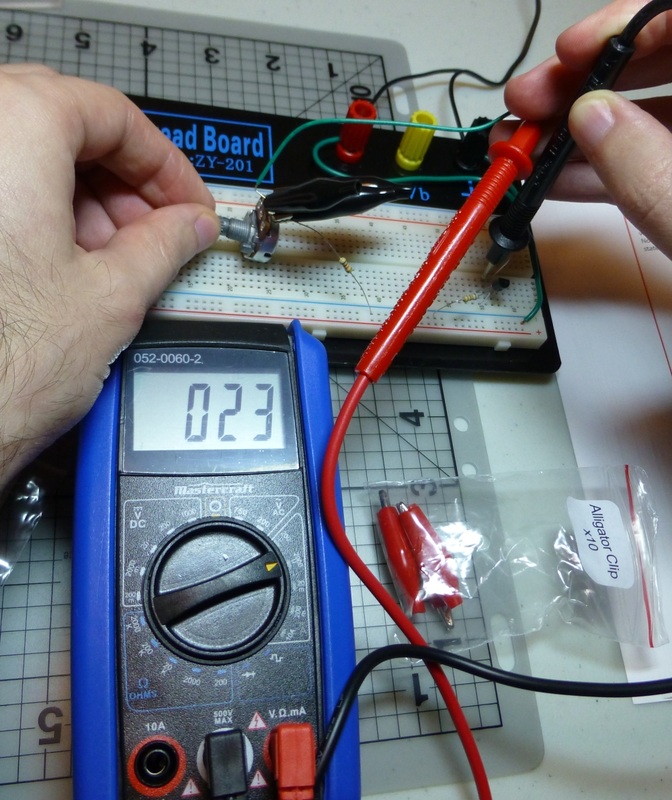
The final part of the experiment involved directly testing the current at different points in the circuit and using a potentiometer to smoothly change the current going to the base.
Sure enough, there was a direct correlation between the current entering the base and the current leaving the emitter, as I had guessed from using my finger-switch.
And now, finally: the next project looks like a "real project", with lots of pieces and a speaker and noodly circuit diagrams OOOOH I can't wait!
 RSS Feed