Fighting Through Frustration
Now that I'm less worried about nuking my components, it's time for my first permanent project! This excites me even more than destroying things. One of the main reasons I want to learn circuitry is to make things that exist, like reallly exist. If I just take it apart at the end of the project, was it really even there?
(Well, yes. That's the point of this blog, to prove that!)
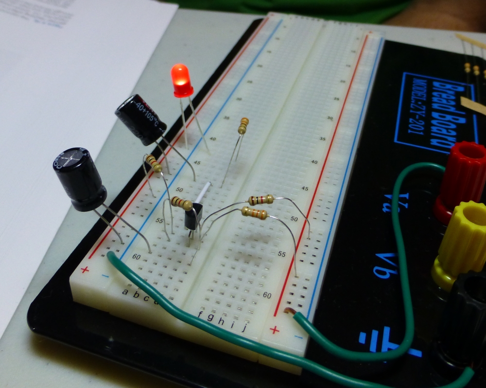
So this project begins with the low frequency pulse module from Project 11. In that project it was used to make a speaker squack, But before we wired up the speaker, we used an LED to test that the pulse was working. Well, we're going back to that: The project is to make a sweet pulsing LED thing!
I began by prototyping the setup on the breadboard. It worked well. Off to a good start! Then the design expanded slightly: one more capacitor after the gate gives the circuit a slow discharge, so the LED pops on and then slowly fades out (slowly meaning about a half second). Then a second later it blinks on again. Pretty cool, pretty pretty!
(Well, yes. That's the point of this blog, to prove that!)
So this project begins with the low frequency pulse module from Project 11. In that project it was used to make a speaker squack, But before we wired up the speaker, we used an LED to test that the pulse was working. Well, we're going back to that: The project is to make a sweet pulsing LED thing!
I began by prototyping the setup on the breadboard. It worked well. Off to a good start! Then the design expanded slightly: one more capacitor after the gate gives the circuit a slow discharge, so the LED pops on and then slowly fades out (slowly meaning about a half second). Then a second later it blinks on again. Pretty cool, pretty pretty!
Alright, so now that I've prototyped it, it's time to get physical! The book contained detailed diagrams for how to lay the components out, where to solder, and so forth, and this time around I was content just to follow the instructions and focus on getting it right.
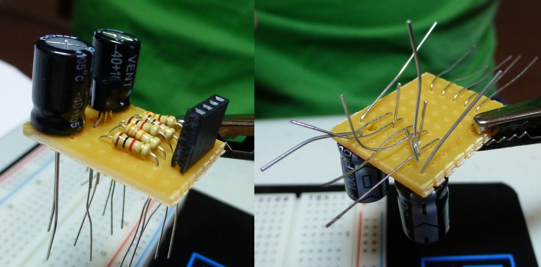
I laid out the components on some perforated board, measured the space they took, and got busy with the utility knife. I couldn't believe how tiny the little board I ended up with was, and was already getting excited for the final result! I also had to hack apart a strip of "sockets" to get just 4 sockets; this is so that it would be easy to swap out the power supply and LED later. I had to crush a 5th socket to get the thing separated, but that's okay! I'm gettin' physical!
After all the cutting was done, I re-inserted the components into the perf board, bent their leads to hold them in place, and got down to the real work: soldering!
(Later, I find out, it's much advised to only insert and solder one or a few components at a time. I can certainly see the wisdom in that after fighting with leads the whole time!)
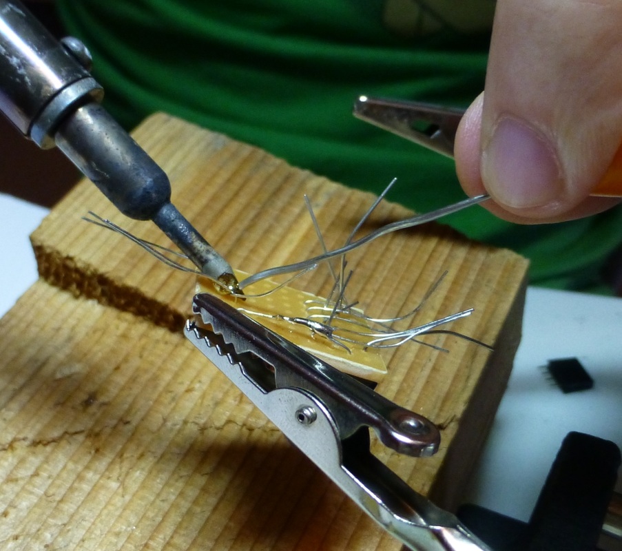
So I soldered my first two wires together, and it went perfectly. The solder did what it should, the iron did what it should, it was clean, and shiny. I grabbed the wire clippers to trim off the excess and snip! sliced off one of the leads. Well, off to a great start!
I considered how I would repair it, and after testing that the leads were fairly rigid and holding themselves in place, opted to go with the "melt a huge blob of solder over the break and hope it still works". In hindsight I should have done a test with the meter here, but it looked just fine so I soldiered on (or soldered on?).
Then things started getting really frustrating. Reaaaaaaaallly frustrating. The solder wouldn't melt, not even when I pressed it right against the well-warmed iron. Except sometimes. I couldn't figure out what was going on, but with much growling and muttering I somehow managed to get solder on every joint (I cheated a lot of them).
There was one short caused by too much solder, I spotted it and hacked away at it with the wire cutters.
But finally, it was all done! By this point I was grumpy and really didn't feel like testing my connections, so I just plugged it in and threw the switch!
The LED lit, but was blinking very rapidly. Something wasn't right...
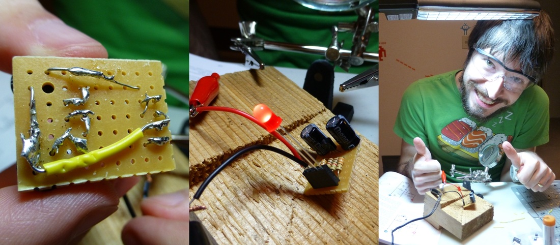
I turned the board over, compared it with the diagrams, and quickly found my mistake, a simple miswire. Fortunately, it was not one of the leads but the single additional piece of white (the yellow bit in the photos), so I snipped it away and attached a new one, with only a minor amount of angry-soldering.
I double checked all the connections and diagrams and then threw the switch again. It worked! It worked!
I had successfully created a BLFNAR.
Technically the project ends by swapping out the AC adapter for a 9v battery, and making it look all pretty, but I am not entirely in the mood. I'll get back to it after I upgrade the alarm system.
I considered how I would repair it, and after testing that the leads were fairly rigid and holding themselves in place, opted to go with the "melt a huge blob of solder over the break and hope it still works". In hindsight I should have done a test with the meter here, but it looked just fine so I soldiered on (or soldered on?).
Then things started getting really frustrating. Reaaaaaaaallly frustrating. The solder wouldn't melt, not even when I pressed it right against the well-warmed iron. Except sometimes. I couldn't figure out what was going on, but with much growling and muttering I somehow managed to get solder on every joint (I cheated a lot of them).
There was one short caused by too much solder, I spotted it and hacked away at it with the wire cutters.
But finally, it was all done! By this point I was grumpy and really didn't feel like testing my connections, so I just plugged it in and threw the switch!
The LED lit, but was blinking very rapidly. Something wasn't right...
I turned the board over, compared it with the diagrams, and quickly found my mistake, a simple miswire. Fortunately, it was not one of the leads but the single additional piece of white (the yellow bit in the photos), so I snipped it away and attached a new one, with only a minor amount of angry-soldering.
I double checked all the connections and diagrams and then threw the switch again. It worked! It worked!
I had successfully created a BLFNAR.
Technically the project ends by swapping out the AC adapter for a 9v battery, and making it look all pretty, but I am not entirely in the mood. I'll get back to it after I upgrade the alarm system.
Heat Shrink Tubing Revisited
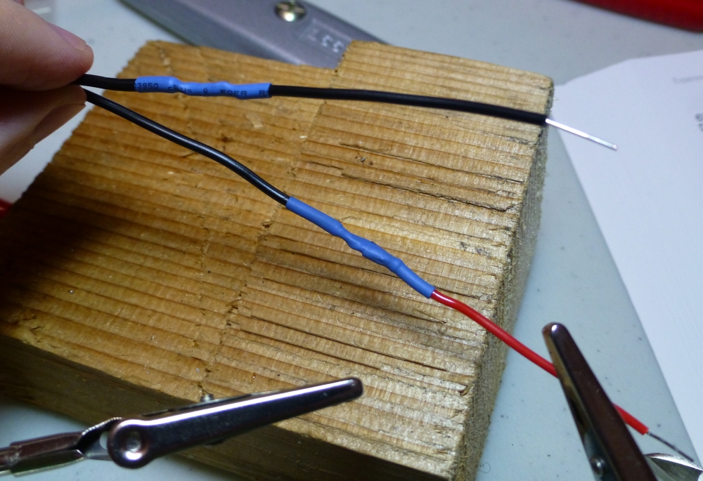
Speaking of getting back to it: At the end of Project 12 I mentioned that I hadn't completed the final part of the project -- adding coloured ends to the AC adapter wires -- because I didn't have a way of dealing with heatshrink tubing.
But then it hit me, of course I have heat! I've heard that you can solder with a lighter, surely you can work heatshrink with one? So I soldered a short red and black 22 gauge wire to the appropriate ends of the cord, put some bits of tube on, and got to work with the barbecue lighter.
Success!
But then it hit me, of course I have heat! I've heard that you can solder with a lighter, surely you can work heatshrink with one? So I soldered a short red and black 22 gauge wire to the appropriate ends of the cord, put some bits of tube on, and got to work with the barbecue lighter.
Success!
 RSS Feed