Expanding My Capacity
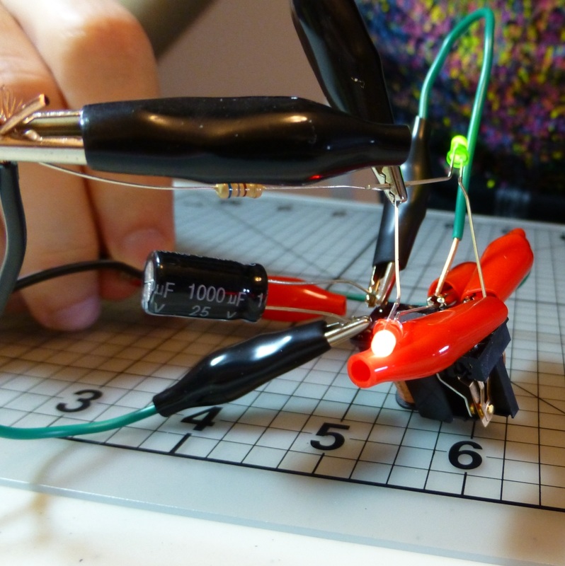
This project began as a modification of the last one. (Foolishly, I didn't look ahead and completely disassembled it, but at least I had the technique for putting it together again. Note for those paying attention to the pictures: the red and green LEDs swapped connections.) The project consisted of two parts: The first was modifying the circuit so that it would switch itself, and the second was putting it on to a breadboard (which I looked forward to eagerly!)
The first part of the mod involved having the "unpowered" output of the relay switch connected to the power for the switch. This means that when the switch is "off", it will provide itself with power to turn on, and when on, it will cut power to turn off again.
I plugged it in and hit the button, and the relay buzzed furiously and both LEDs appeard to glow dimly. I read on and discovered that this is a great way to burn out your relay, but what the heck, I've already destroyed the casing on this one, right?
So the second mod was to put in a capacitor between the positive and negative terminals of the relay. The idea is that while the switch is off (and thus has power flowing to it to turn it on), it will simultaneously charge the capacitor. As it switches on and kills power to the switch, the capacitor discharges so the switch remains on for a second or so. Once it's discharged, the relay will close, sending power to the switch and capacitor once more.
Wiring this up worked thus: The relay remained "on" most of the time, and upon turning off would immediately flick on again, about once per second. Tick, tick, tick, tick....
Begone, Alligator Clips!
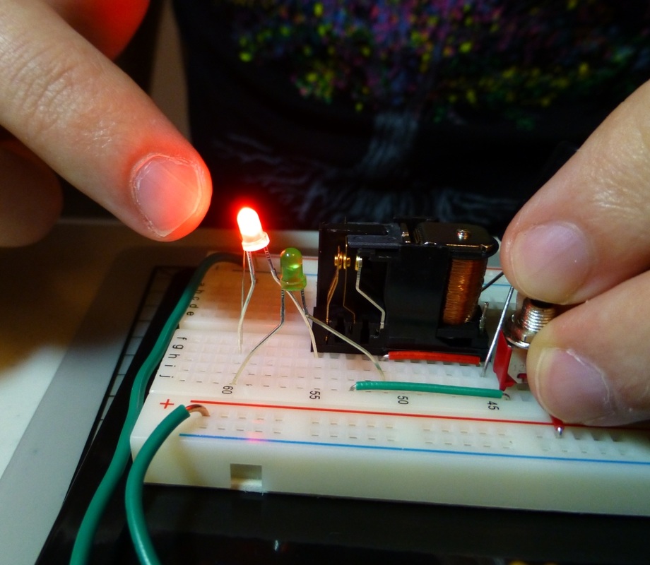
And now, finally, I get to bring out the breadboard! There's two reasons I've been looking forward to this: The first is that dealing with the alligator clips has been a pain right for the beginning (I learned my lesson; patch cables are in the mail!), and the second is that I think projects just look so much cooler and more professional on a breadboard. Heheh.
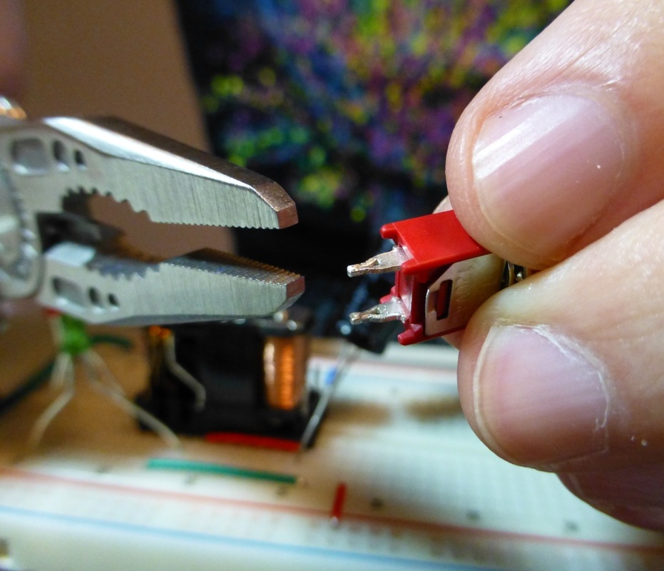
Assembling the breadboard and transferring the circuit over was straightforward, except that I had to crush down the little footies on the pushbutton switch to get it to fit in the breadboard. It was also interesting using the pre-cut jumper wires that came with the kit: Each wire is cut to a specific length to span a certain number of holes in the breadboard, and sorted by colour. (I think I have a side project in the near future of writing up a cheatsheet of which colour is which length.)
Once assembled I pressed the button and the lights did the clicky-switchy thing they're supposed to. Woo!
The next project looks like it's going to expand on this capacitor trick a bit.
 |  |
 RSS Feed