I Just Built My First Synthesizer!
This project was a nice extension of the last one, using both capacitors and amplifying transistors. The goal is to build a modular circuit that produces an alarm noise through a mini speaker.
This idea of modularity seems really important. In my day job I do computer programming, and it's really important to always break the problem down into a bunch of small problems, and then hook them together to solve the larger problem again. Although it's obvious in hindsight to solve electronics problems this same way, I didn't think of it and it's great to see that Make: Electronics is introducing this approach to building out your circuits.
It also occurs to me that the modules I'm about to build could probably stand in for integrated circuits (microchips) in the future, so thinking about how to solve a problem by connecting pieces of functionality (such as a timer, amplifier, etc.) is valuable.
The first module was described as an oscillator. It used a new component called a Programmable Unijunction Transistor (PUT) which worked quite differently from the transistors I was using last project. Whereas the P2N2222A could be used for "switching" or "amplification", I would describe the 2N6027 PUT as used for "gating". Basically, it will only let a current through the main circuit if it's voltage is higher than a certain value -- and that value can be "programmed" using the third pin (in the same way the third pin "switches" the 2222).
In a nutshell, a capacitor would charge, and once it's voltage was high enough, it would be able to pass the gate in the PUT and suddenly drain. This would cause an LED to blink. Then it's voltage was low, the gate would be impassable, and the process would start again. This gives us a periodic pulse, with the suggested components about twice a second.
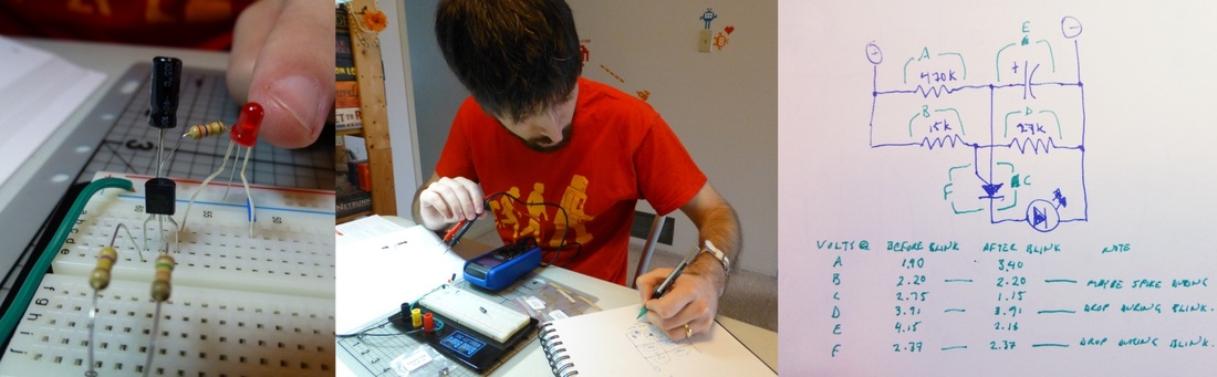
I spent a considerable amount of time probing around this circuit, even going to far as to write out a table of voltages. It was nice to see what was going on in the circuit and by the end I had a pretty clear idea of how the electricity was flowing around.
The second module was a high-frequency oscillator. This circuit was basically identical to the first module, but by having a tiny capacitor and and a very low threshold on the PUT, it would charge and discharge thousands of times per second.
The project kit came with a baggie of tiny capacitors, each with itty bitty writing on the side, and I had to look up their codes online in order to find the one with the value I was looking for.
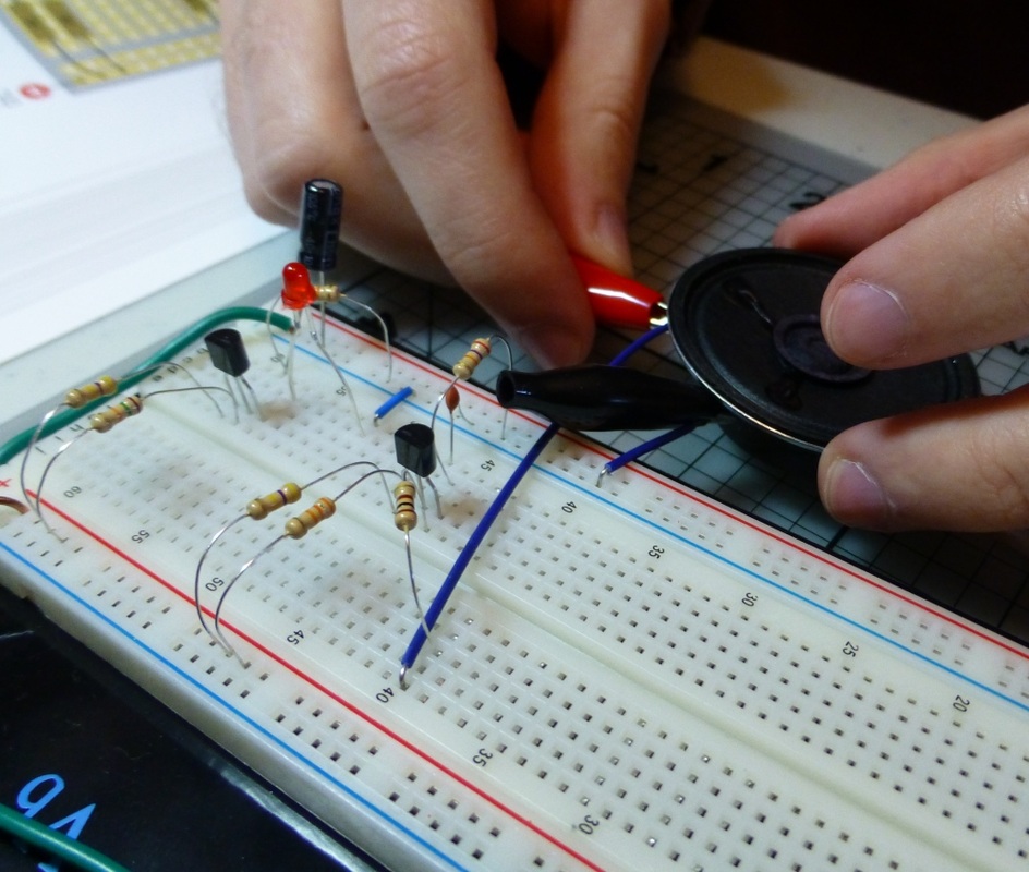
Because this oscillation was so high frequency, it would have not created visibly blinking in an LED so it gets wired up to a mini loudspeaker instead. Throwing on the power switch, my light continued to blink, and the speaker emitted a very very faint whistling noise.
The project kit came with a baggie of tiny capacitors, each with itty bitty writing on the side, and I had to look up their codes online in order to find the one with the value I was looking for.
Because this oscillation was so high frequency, it would have not created visibly blinking in an LED so it gets wired up to a mini loudspeaker instead. Throwing on the power switch, my light continued to blink, and the speaker emitted a very very faint whistling noise.
The third module to create was an amplifier, to make the noise louder! This meant pulling out the 2222 transitors again, and using that to amplify the oscillations. The project ends up building two amplifiers side-by-side in order to get the volume up to a nice loud level. (Though if I ever rebuild this circuit, I'd probably leave on off, as the sound made by this thing is pretty annoying!!)
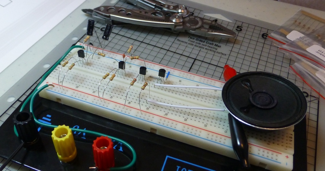
The final step of the project was to wire the original oscillator in to the other circuit (up til now it just sat there blinking it's LED). With the combination of the low frequency and high frequency oscillators (and an extra capacitor to round off an edge in the pulses), the speaker produced a "woop woop woop!" sound much like a car alarm. Fantastic!
The final step of the project was to wire the original oscillator in to the other circuit (up til now it just sat there blinking it's LED). With the combination of the low frequency and high frequency oscillators (and an extra capacitor to round off an edge in the pulses), the speaker produced a "woop woop woop!" sound much like a car alarm. Fantastic!
Time to Play Around
By this point in the project, I had noticed something very disturbing: Almost every resistor on the board was a different value. I had a vague idea why some were high values and some were low values, but no clue why any was a specific value. For example, the resistors guarding the amplifying transistors were 2.2 kiloohms and 100 ohms. That's a pretty large difference, but it appears to me that the parts are serving roughly the same function. Obviously one is farther along a chain of amplification so it's not surprising that they are different, but why are the different? And why by those values?
No answer seemed to be emerging, so I started playing with the components instead. At the beginning when I was measuring the circuit, I had swapped out the capacitor for a larger one, which resulted in a dramatic slowing of the oscillation. This had allowed me to watch the voltages on my meter as they slowly changed, instead of them all just flickering around.
Well since I understood that this circuit was basically generating and combining waves, and since I have a basic understanding of sound synthesis, I decided to try swapping out capacitors again to see what different sounds I could make. A larger capacitor on the high frequency oscillator lowered the overall pitch of the alarm, and a larger capacitor in the first oscillator decreased the frequency of the "woops". A larger capacitor in the final position, changed how far each "woop" would sweep,
I am regretting not recording the delightful noises this thing was making! Oh well, perhaps next time. It's also worth noting that the whole thing took a few seconds to "warm up" and "cool down" as the chain of capacitors filled and emptied. During these times there were lots of interesting bweeps and blorps.
And that wraps up chapter 2 of the book! The next chapter introduces soldering, and the shopping list includes some permanent project boxes, so I'm looking forward to building something and not taking it apart!
And that wraps up chapter 2 of the book! The next chapter introduces soldering, and the shopping list includes some permanent project boxes, so I'm looking forward to building something and not taking it apart!
 RSS Feed